
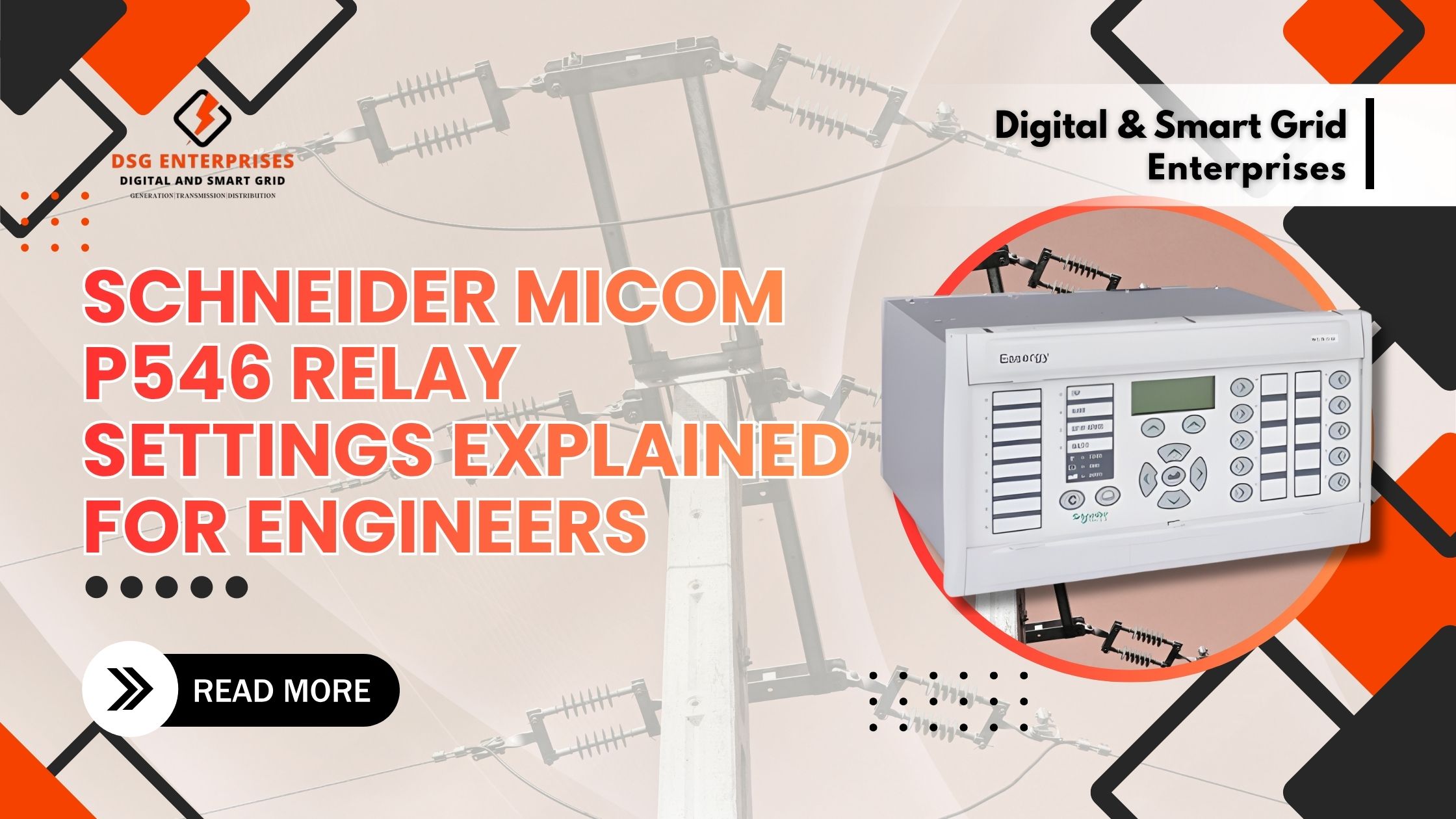
When it comes to protecting critical electrical infrastructure, the Schneider MiCOM P546 stands as one of the most sophisticated protection relays available in the market today. This comprehensive guide walks engineers through the essential settings, features, and practical applications of the Schneider MiCOM P546 Protection Relay, ensuring optimal performance and reliability in power system protection.
Understanding the Schneider MiCOM P546 Protection Relay
The MiCOM P546 Protection Numerical Relay represents a significant advancement in feeder management and motor protection technology. Designed by Schneider Electric, this intelligent electronic device (IED) combines multiple protection functions, control capabilities, and monitoring features into a single, compact unit. For engineers working in industrial facilities, power distribution networks, and critical infrastructure projects, understanding this relay’s capabilities is essential.
What Makes the MiCOM P546 Stand Out?
- Comprehensive Protection Portfolio: The Schneider MiCOM P546 offers an extensive range of protection functions, including overcurrent, earth fault, directional, thermal overload, and motor protection features. This makes it suitable for diverse applications from simple feeder protection to complex motor control scenarios.
- Advanced Communication Capabilities: Built with modern substations in mind, the relay supports multiple communication protocols, including IEC 61850, Modbus, and DNP3, enabling seamless integration into SCADA systems and substation automation architectures.
- User-Friendly Interface: Despite its sophisticated functionality, the relay features an intuitive graphical display and straightforward navigation, reducing configuration time and minimizing the learning curve for engineering teams.
Essential Settings Every Engineer Should Know
Overcurrent Protection Settings (ANSI 50/51)
- Instantaneous Overcurrent (50): This function provides high-speed protection against severe fault conditions. Engineers should configure the pickup current typically between 8-20 times the nominal current, depending on the system’s fault level and coordination requirements.
- Time Delayed Overcurrent (51): This setting follows standardized curve characteristics (IEC or IEEE). The time multiplier setting (TMS) determines how quickly the relay operates at various fault current levels. Proper coordination with upstream and downstream devices is crucial to maintain selectivity.
- Curve Selection: The MiCOM P546 Protection Numerical Relay offers multiple curve types, including Standard Inverse (SI), Very Inverse (VI), Extremely Inverse (EI), and Long Time Inverse. Selection depends on the specific coordination study requirements and system characteristics.
Earth Fault Protection (ANSI 50N/51N)
- Sensitive Earth Fault Detection: The relay can detect low-magnitude earth faults that might otherwise go unnoticed. Engineers should set the earth fault pickup between 5-20% of the nominal current for sensitive protection.
- Directional Earth Fault: For systems requiring directional sensitivity, the relay’s directional earth fault protection prevents unnecessary tripping on faults occurring outside the protected zone. The polarizing quantity and characteristic angle must be carefully configured based on system grounding practices.
- Time Grading: Similar to phase overcurrent protection, earth fault time grading ensures selective fault isolation, minimizing the affected area during ground fault conditions.
Motor Protection Features
Thermal Overload Protection (ANSI 49): The Schneider MiCOM P546 Protection Relay incorporates sophisticated thermal modeling that accounts for motor heating characteristics, ambient temperature, and cooling time constants. Engineers must input accurate motor thermal data, including:
- Full load current rating
- Service factor
- Thermal time constant at locked rotor
- Cooling time constant
- Safe stall time
Locked Rotor Protection (ANSI 14): This prevents motor damage during prolonged starting or stalling conditions. The pickup current should be set slightly above the motor’s locked rotor current, with a time delay sufficient to allow normal starting but fast enough to prevent thermal damage.
Start-Up Supervision: The relay monitors starting time and frequency, preventing excessive starts that could damage the motor windings. Engineers should configure the maximum starting time based on manufacturer specifications and allowable starts per hour.
Voltage Protection Settings
- Undervoltage Protection (ANSI 27): Protects motors and equipment from sustained low voltage conditions. Typical settings range from 80-90% of nominal voltage with time delays between 1-10 seconds to ride through transient voltage dips.
- Overvoltage Protection (ANSI 59): Guards against insulation stress and equipment damage. Settings typically range from 110-120% of nominal voltage with adjustable time delays based on equipment withstand capabilities.
- Phase Unbalance Protection (ANSI 46): Critical for motor protection, this function detects negative sequence current or voltage. Engineers should set the threshold between 10-30% unbalance, depending on motor tolerance.
Communication and Integration Settings
IEC 61850 Configuration
The MiCOM P546 Protection Numerical Relay fully supports IEC 61850 substation automation standards. Engineers must configure:
- IED Name and IP Address: Unique identification within the substation communication network ensures proper data exchange and prevents addressing conflicts.
- GOOSE Messaging: Generic Object-Oriented Substation Event messages enable high-speed peer-to-peer communication between IEDs. Proper configuration of GOOSE datasets and control blocks is essential for interlocking and fast transfer schemes.
- Logical Nodes: The relay’s functionality is organized into standardized logical nodes. Understanding the logical node structure helps engineers implement proper SCADA mapping and data acquisition.
Modbus and DNP3 Protocol Settings
- Register Mapping: For facilities using Modbus or DNP3, engineers must configure the appropriate register addresses for measurements, status points, and control commands.
- Communication Parameters: Baud rate, parity, stop bits, and device addressing must align with the master station configuration. Typical settings include 9600 or 19200 baud with even parity.
- Polling Intervals: Optimization of polling intervals balances data freshness with communication bandwidth, particularly important in systems with multiple relays on a shared communication link.
Disturbance Recording and Event Logging
Fault Record Configuration
- Pre-Fault and Post-Fault Recording: The relay captures waveforms before and after fault events. Engineers should configure sufficient pre-trigger time (typically 50-200ms) to capture the system state leading up to the fault.
- Sampling Rate: Higher sampling rates provide better waveform resolution for fault analysis. The Schneider MiCOM P546 offers configurable sampling rates up to 128 samples per cycle.
- Trigger Conditions: Defining appropriate trigger conditions ensures that important events are captured without filling memory with insignificant disturbances.
Event Sequencing
- Time Stamping Accuracy: With GPS or IRIG-B synchronization, the relay achieves microsecond-level time stamping accuracy, essential for sequence-of-events analysis across multiple devices.
- Event Buffer Capacity: Understanding the event buffer size helps engineers determine appropriate data retrieval intervals, preventing loss of historical data.
Practical Considerations for Field Engineers
Commissioning Best Practices
- Primary Injection Testing: Validates current transformer connections and relay pickup settings. Engineers should verify that measured currents match injected values within acceptable tolerances (typically ±5%).
- Secondary Injection Testing: Confirms protection function operation, timing characteristics, and logic sequences without energizing the primary system.
- Communication Testing: Verification of SCADA points, alarm transmission, and remote control functions ensures complete system integration.
Coordination Studies Integration
The protection settings configured in the MiCOM P546 Protection Numerical Relay must align with the overall system coordination study. Engineers should:
- Maintain Selectivity: Ensure time-current characteristic curves provide adequate discrimination margins (typically 0.3-0.4 seconds at fault current levels).
- Consider Arc Flash Impact: Protection settings directly affect incident energy calculations. Faster clearing times reduce arc flash hazards and improve personnel safety.
- Document Settings: Comprehensive documentation of relay settings, including rationale and calculation references, facilitates future modifications and troubleshooting.
Finding the Right MiCOM P546 Protection Numerical Relay Supplier
Key Supplier Selection Criteria
- Technical Support Capabilities: A reliable MiCOM P546 Protection Numerical Relay Supplier should offer comprehensive technical assistance, including pre-sales application engineering and post-sales commissioning support.
- Delivery and Lead Times: Critical projects require suppliers with adequate inventory and efficient logistics to meet project schedules.
- Training and Documentation: Quality suppliers provide operator training, maintenance workshops, and complete technical documentation to support long-term operation.
Understanding MiCOM P546 Protection Numerical Relay Price
Value Beyond Initial Cost: While the MiCOM P546 Protection Numerical Relay Price represents a significant investment, engineers should evaluate the total cost of ownership, including:
- Reduced maintenance requirements compared to electromechanical relays
- Multi-function capability eliminates the need for multiple protection devices
- Advanced diagnostic features reduce troubleshooting time
- Extended service life and reliability
Price Factors: The relay price varies based on configuration options, communication protocol requirements, and quantity ordered. Engineers should work with suppliers to optimize specifications against budget constraints.
Conclusion
The Schneider MiCOM P546 Protection Relay represents a powerful tool for modern power system protection. By understanding the essential settings covered in this guide, from overcurrent and earth fault protection to motor protection features and communication configuration, engineers can fully leverage this relay’s capabilities to ensure reliable, safe, and efficient operation of electrical infrastructure.
Proper configuration requires careful attention to system requirements, thorough coordination studies, and adherence to industry standards. Whether you’re commissioning a new installation or optimizing existing protection schemes, the principles and practices outlined here provide a solid foundation for working with the Schneider MiCOM P546.
We, Digital and Smart Grid Enterprises, are the leading Schneider Relay Suppliers, traders, distributors, and exporters in India, so contact us to get Schneider Numerical Relays Price List | Get a Quote. Schneider Relays are a wide range of medium-voltage and high-voltage protective applications. We have a large selection of Schneider MiCOM, VAMP, SEPAM, and Easergy Relays. Get Schneider Numerical Relays For Your Power System Now. For Schneider MiCOM P546 Protection Relay prices or product inquiries, you can reach us at +91 7021624024 or email info@dsgenterprises.in. With strong technical expertise, our team supports you at every step from selecting the right product to providing complete after-sales assistance. Explore our full range of products by clicking here for more details

