
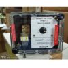

ALSTOM Definite Time Delay Relay VTT11ZG8053BCH
Description
ALSTOM Definite Time Delay Relay VTT11ZG8053BCH
ALSTOM Definite Time Delay Relay VTT11ZG8053BCH
• Type: Electro Mechanical Relay
• Protection Type: Definite Time Delay Relay
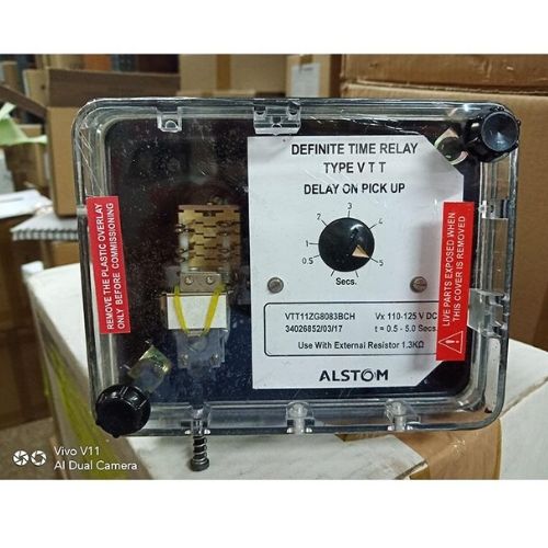
VTT11ZG8053BCH
STATIC DEF TIME DELAY RELAY WITH DELAY O
Technical Specifications
Model No : VTT11ZG8053BCH
VTT11
Application – Pick Up
Aux. Voltage – 220 – 230 V dc
Case Size – 1/2N H 12T
Contacts – 2 N/O 2 N/C S/R
Flag – Yes
Mounting – Flush
Timing Range – 0.5 – 5 Secs.
External Resistor 3.3 K.OHMS 35 Watts
Name Plate RZF9066-601
Outline Diagram MFM017 & FJ0349
Wiring Diagram MZDZ601.01-2
VTT11ZG8053BCH ALSTOM Relay Features
Low burden, static
- Accurate and
- Immune to transient and surges; withstands 5 kV impulse voltage
General Description
Phase difference measurement Phase measurement is achieved by algebraically subtracting the two supply voltage waveforms and comparing the resultant modulated beat waveform envelope with a dc reference voltage (See Figure 1).
The dc reference is proportioned to the sum of the peaks of the two supply voltages to provide phase measurement independent of supply voltage variation. Referring to Figure 2, the resulting voltage produced after subtraction is passed via the gate (which is opened when the VTI supply is present) to the phase angle comparator and integrating amplifier.
The signal is compared with the dc reference and produces a smoothed output to the relay drive unit if the signal is less than dc reference. The relay drive circuit prevents chatter of the relay at the just-operate condition.
Frequency difference measurement Frequency difference measurement is achieved by checking that the phase angle traversed in a defined period is less than
a pre-determined value. Referring to the block diagram the output from the phase measurement circuit drives an accurately calibrated timer. The timer operates the relay on completion of its timing cycle, if the output from the phase measurement circuit persists.
The relationship between timer setting and frequency difference is given in Table 1.
Voltage difference measurement Two types of voltage lockout are available. Type SKD compares the amplitude of the two supply voltages, with a stabilized dc reference which is proportioned to the nominal supply voltage. The Voltage lockout circuit inhibits the gate if either voltage is below the preset limit. Type SKE compares the two supply voltages and inhibits the gate if the difference between the supply voltages exceeds the preset limit.
To explore the comprehensive range of GE/ Alstom Auxiliary, Tripping and lockout relays click here!


Reviews
There are no reviews yet.