

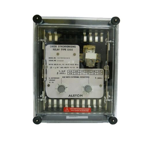
GE / Alstom check Synchronising Relay SKE11BF8002BCH
Description
GE / ALSTOM CHECK SYNCHRONISING RELAY SKE11BF8002BCH
Check Synchronising Relay SKE11BF8002BCH Technical Specification
- Type: Electro Mechanical Relay
- Protection Type: Check Synchronizing Relay
GBSKE11BF8002BCH
CHECK SYN RELAY FOR MANUAL SYN OF GENERA
| Technical Specifications | |
| Model No : | SKE11BF8002BCH |
| Relay type | SKE11 |
| CASE SIZE | 1D V 20T D/E |
| Aux. voltage | 110/125 V DC |
| MTA Phase-Char Angle | 20 Degrees |
| Voltage Lockout Adjust | 2 – 10 % |
| CONTACTS | 2 N/O S/R |
| Timing Range | 0.5 – 3.0 Secs |
| Frequency | 50 Hz / 60 Hz |
| V.T/P.T Secondary | 63.5 / 110 V AC |
| FLAG | No |
| MOUNTING | Flush |
| External Resistor | 1 K Ohm 35 Watts |
| Name Plate | MZF9008-002 |
| Outline Diagram | MFJ012 <(>&<)> FJ0349 |
| Wiring Diagram | MBDZ608-1 |
Check synchronising relays are used to prevent interconnection of badly synchronised supplies. Type SKD relays are generally used in auto reclosing sequence of interconnectors along with the auto reclosing relay. Type SKE relays are used to safeguard manual synchronising of generators.The check synchronising relay contacts are normally connected in series with the circuit breaker closing circuit and ensures that the differences in phase, voltage and frequency are within pre-selected limits before switching in an incoming alternator or interconnecting two sections of a power system.
Check Synchronising Relay SKE11BF8002BCH Features
- Low burden, static
- Accurate and
- Immune to transient and surges; withstands 5 kV impulse voltage
General Description
Phase difference measurement Phase measurement is achieved by algebraically subtracting the two supply voltage waveforms and comparing the resultant modulated beat waveform envelope with a dc reference voltage (See Figure 1).
The dc reference is proportioned to the sum of the peaks of the two supply voltages to provide phase measurement independent of supply voltage variation. Referring to Figure 2, the resulting voltage produced after subtraction is passed via the gate (which is opened when the VTI supply is present) to the phase angle comparator and integrating amplifier.
The signal is compared with the dc reference and produces a smoothed output to the relay drive unit if the signal is less than dc reference. The relay drive circuit prevents chatter of the relay at the just-operate condition.
Frequency difference measurement Frequency difference measurement is achieved by checking that the phase angle traversed in a defined period is less than
a pre-determined value. Referring to the block diagram the output from the phase measurement circuit drives an accurately calibrated timer. The timer operates the relay on completion of its timing cycle, if the output from the phase measurement circuit persists.
The relationship between timer setting and frequency difference is given in Table 1.
Voltage difference measurement Two types of voltage lockout are available. Type SKD compares the amplitude of the two supply voltages, with a stabilised dc reference which is proportioned to the nominal supply voltage. The Voltage lockout circuit inhibits the gate if either voltage is below the preset limit. Type SKE compares the two supply voltages and inhibits the gate if the difference between the supply voltages exceeds the preset limit.
To explore the comprehensive range of GE/ Alstom Auxiliary, Tripping and lockout relays click here!


Reviews
There are no reviews yet.